– A Comprehensive Overview from Drilling Risks to Cost –
15% of Japan’s tap water comes from groundwater (Japan Water Works Association, 2024).
Some cities, such as Kumamoto and Akishima, rely 100% on groundwater for their tap water. However, many municipalities abandon groundwater use during the survey stage. This article summarizes five key chapters on the critical points to consider when adopting groundwater as a water source.
Water Volume & Quality — Conditions for “Hitting the Jackpot”
| Aspect | Required Condition | Survey Phase |
|---|---|---|
| Volume | At least 80 L/min per well* | Pumping test after drilling |
| Quality | Iron, manganese, salt, arsenic within standards or within treatable cost | Water quality test after drilling |
| Long-Term Stability | Low risk of land subsidence or saltwater intrusion | Planning stage |
“You won’t know water volume or quality until you dig”—this is the biggest risk of groundwater development.
Learning with an Underground Diagram
Where exactly is groundwater stored underground? Have you ever wondered where the water you use every day comes from beneath your feet?
The illustration in Figure 1 helps explain the underground conditions where groundwater is found.
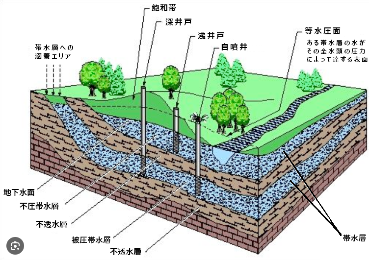
Figure 1: Underground Stratification and Aquifer Structure
Key Points to Understand Groundwater
- Aquifer: Layers of gravel/sand that hold water like a sponge
- Aquitard: Layers of clay or bedrock that block water flow
- Water above the aquitard = Unconfined Groundwater (shallow well) → Easily affected by surface conditions
- Water below the aquitard = Confined Groundwater (deep well) → Generally better water quality
Well Drilling: Survey → Drilling → Pumping Test → Water Quality Test → Evaluation
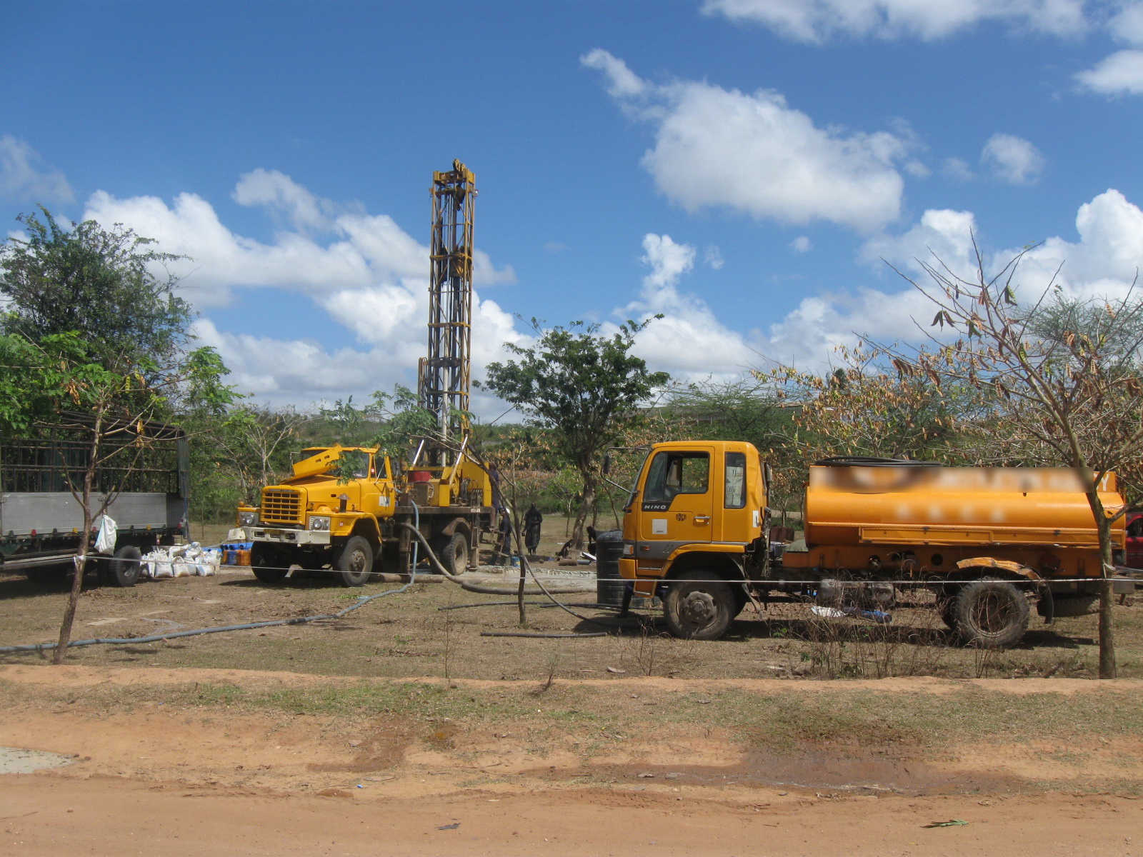
Exploration and Field Survey in Well Drilling
In well drilling, determining the drilling location is a crucial factor. Typically, the location is selected based on two comprehensive viewpoints:
- Results from field surveys conducted by hydrogeology experts (specialists in groundwater flow and distribution)
- Subsurface data inferred from geophysical surveys conducted by specialists in physical exploration
Exploration Flow
- Collection of existing well data and geological maps
- Electrical resistivity surveys (e.g., 2D resistivity) to estimate aquifer zones
- Hydrogeologists conduct field surveys to narrow down drilling sites (approx. 1 month)
*Field surveys may be conducted before or after electrical surveys as needed.
*Hydrogeologists specialize in groundwater flow and distribution.
About Electrical Exploration
- Vertical Exploration: The most common method, analyzing the vertical structure at a single point (1D profile)
- 2D Resistivity Exploration: A more advanced method that aligns multiple vertical surveys linearly to capture a broader underground profile
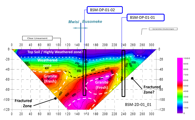
Process for Finalizing Drilling Location
By collecting data from multiple underground cross-sections, we make comprehensive decisions on whether to drill and where, based on:
- Distribution of aquifers underground
- Thickness of aquifers in the vertical direction
- Positional relationships between aquifers and aquitards
- Results of field surveys by hydrogeology experts
- Historical well drilling data from nearby areas
Through this scientific and comprehensive approach, we select the optimal drilling site in terms of water quantity and quality.
Based on this outcome, the final decision to drill is made and the well is constructed.
Pumping Test and Evaluation Criteria
| No. | Water Volume (L/min)* | Evaluation | Use |
|---|---|---|---|
| 1 | 0 | Fail | — |
| 2 | 1–15 | Fail | — |
| 3 | 15–80 | Conditional Pass | Hand pump |
| 4 | 80+ | Pass | Submersible pump + tap water supply |
*The water volume threshold is set based on the scale, nature, and difficulty of groundwater development.
*The pumping test includes a series of preliminary, step-wise, continuous, and recovery pumping tests.
Water Quality Tests and Treatment Standards
| Item | Standard | Contamination Risk | Treatment Method | Difficulty/Cost |
|---|---|---|---|---|
| Iron/Manganese | Fe ≤ 0.3 mg/L Mn ≤ 0.05 mg/L | High | Aeration/chlorination + filtration; biological treatment | Moderate / Depends on method |
| Arsenic | ≤ 0.01 mg/L | High in specific regions | Co-precipitation with iron (biological) | Low if iron is present |
| Fluoride | ≤ 0.8 mg/L | Rare in Japan | Specialized ion treatment | High |
| Nitrogen Compounds | NO3+NO2 ≤ 10 mg/L NO2 ≤ 0.04 mg/L* | Depends on region | Biological treatment | Sometimes difficult / Depends on concentration |
*The NO2 (nitrite) threshold is a voluntary management target, not a legal standard.
Is Well Drilling a Gamble? Assessing Uncertainty
As outlined above, well drilling involves extensive research and site selection. However, in the end, whether the well will be successful often comes down to luck.
Even when using data such as nearby well records, geological surveys, and electrical resistivity tests, the underground conditions remain uncertain until drilling is actually performed. That is the core uncertainty of groundwater development.
Moreover, even if the water volume meets criteria after drilling, the water quality may lead to a decision not to use that well.
In large-scale projects where 100 wells are drilled with the aim of securing 80–90 successful wells, data from failed wells can be used to improve accuracy in future drilling efforts.
On the other hand, in single-well projects, the outcome can heavily rely on chance, and clients must understand and accept this uncertainty.
Structure of a Well
Structure of a Shallow Well
When you imagine a well, you may think of something like an old castle courtyard well—wide enough to drop a bucket in, visible water surface, and operated by a rope and pulley. This image typically corresponds to the structure of a shallow well.
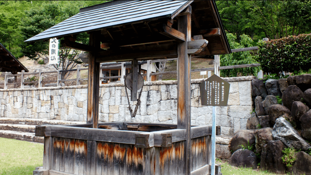
Main characteristics include:
- Opening diameter: approx. 1–2 meters
- Open-type well, sometimes covered as needed
- Water surface visible from the top
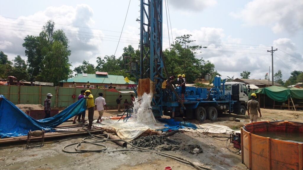
Structure of a Deep Well
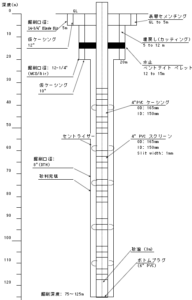
Deep wells have a completely different structure and require several construction steps:
- Casing Installation
- Immediately after drilling, PVC pipes (casings) are inserted to prevent collapse of the borehole walls
- Casings include solid pipes and slotted screen pipes, which are combined
- Screens are placed in aquifer zones to allow water intake
- Gravel Packing
- Gravel is packed between the casing and borehole wall
- This prevents fine sand inflow and provides a filtration effect
- Sealing
- Clay or cement is poured above the gravel to prevent surface contaminants
- Wellhead Protection
- The wellhead is sealed with concrete and a steel cover to prevent accidental contamination
Due to the casing pipe structure, deep wells are also referred to as “pipe wells” or “tube wells.”
Structural Differences and Impact on Water Quality
The structural differences between shallow and deep wells significantly affect water quality. Deep wells, with their sealed design, prevent contamination from surface pollutants, making them more suitable for safe water supply.
After drilling, PVC casings and screen pipes are inserted to stabilize the borehole and allow water intake. Gravel is filled around the casing to prevent inflow of fine particles and assist filtration. Clay or cement seals the upper portion to block surface contamination. Finally, the wellhead is protected with a concrete and steel cover.
Thus, deep wells are also known as “pipe wells” or “tube wells.”
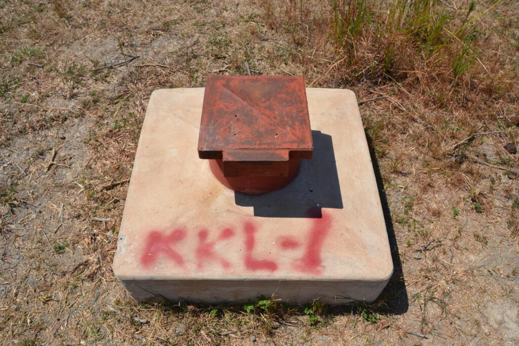
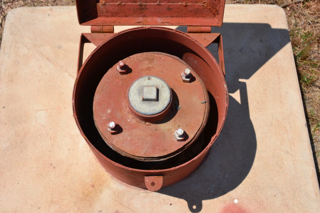
Fully protected wellhead after construction
Estimated Cost of Well Drilling
Drilling a well involves considerable expense.
Costs vary between shallow and deep wells. Here, we introduce examples for (1) deep well drilling and (2) exploration for determining drilling location.
These figures are for reference only, as actual costs depend on conditions. Also note that the drilling costs are converted from overseas estimates made around 15 years ago, and may differ from actual costs in Japan.
Example Cost for Deep Well Drilling (100m Depth)
■ Exploration: approx. ¥3,000,000
– Collection of existing data, field survey, geophysical survey, analysis, and report
■ Well Drilling: approx. ¥3,000,000
– Mobilization/demobilization of drilling equipment: approx. ¥1,000,000
– Drilling work (100m): approx. ¥2,000,000
■ Pump & Facilities: from approx. ¥5,000,000
– Submersible pump, piping, control panel, pump house construction, etc.
◎ Total: from approx. ¥11,000,000
Exploration Work for Deep Wells
In a past project involving exploration of four underground cross-sections to determine the drilling site, the cost (including data collection, field survey, analysis, and report) was around ¥3,000,000.
Drilling Costs for Deep Wells
Drilling costs include the following:
1) Equipment transport and removal: ¥1,000,000
2) Drilling work: ¥2,000,000
- Cost depends on drilling depth
- Well logging (to determine screen/casing positions)
- Casing installation
- Gravel and clay filling
- Well cleaning and pumping test
- Water quality test
- Wellhead protection work
- Drilling report
Note: These costs do not include post-drilling components such as submersible pump installation, control panels, and piping.
Pump and Auxiliary Equipment
After drilling, a submersible pump is installed based on the required water supply capacity, along with a control panel and internal piping in the pump house. Construction of the pump house and equipment may cost at least an additional ¥5,000,000.
Considerations for Using Groundwater
Once groundwater development is complete and a deep well water supply system is constructed, if the water quality meets potable standards without treatment, the running cost is extremely low. Operation mainly requires electricity for pumping, minimal disinfectant chemicals, and periodic pump maintenance.
Although initial construction costs are significant, if the facility can be used for 50 to 100 years, the annualized cost becomes very economical.
However, as with any water supply system, proper maintenance is essential to manage the inherent risks. Groundwater facilities may face the following challenges:
- Future changes in water quality (e.g., salinization, iron or manganese contamination)
- Land subsidence due to excessive groundwater extraction
- Groundwater depletion or flow changes due to earthquakes or subsurface shifts
- Equipment failures, such as pump or control system malfunctions, and the need for routine maintenance
That said, every type of water supply system has its own unique risks. The key is to ensure appropriate operation and risk management based on the characteristics of the facility.
Conclusion
This article introduced key considerations for using groundwater in water supply facility construction—from well structures and drilling methods to associated costs. While some technical aspects were simplified, we hope this article has given you a comprehensive overview of well construction.
If you have any further questions or would like more detailed explanations on specific topics, please feel free to contact us through our inquiry form.